
Membuat Robot Avoider Menggunakan Arduino
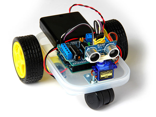
Mini Avoider Robot
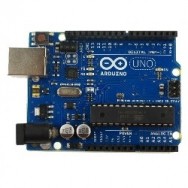
Arduino Uno adalah sebuah papan sistem mikrokontroler AVR. Meskipun mikrokontroler tidak secanggih mikroprosesor seperti intel atau AMD, mikrokontroler malah lebih mudah untuk digunakan mengintekrasikan mesin digital dengan lingkungan fisik.
Arduino Uno memiliki fasilitas input dan output digital maupun analog, sehingga kita bisa menggunakannya untuk banyak aplikasi seperti pencahayaan LED, menggunakan sensor, menjalankan motor dc, dan lain sebagainya.
Pada kesempatan kali ini, kita akan menggunakan Arduino ini untuk membuat robot, Robot kali ini bukanlah robot yang dikontrol menggunakan remote tetapi, memiliki program yang menjadi acuannya untuk mengambil keputusan. Robot ini akan menghindari halangan dan mencari jalan lain.
Kita akan membahas cara membuat robot Arduino penghindar halangan ini dalam dua bagian. Bagian pertama tentang cara merakit komponen penyusunnya dan bagian kedua yaitu tentang pemrogramannya.
Komponen Yang Dibutuhkan
Hal pertama yang perlu kita lakukan adalah mempersiapkan komponen-komponen yang dibutuhkan. Tujuan dari pembahasan ini salah satunya adalah membuat robot semurah mungkin namun tetap dapat menjalankan fungsinya dengan baik. Yah, karna kantong saya terbatas, maka saya mencoba membuatnya semurah mungkin. Saya rasa temen-temen juga setuju dengan saya.. :)
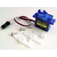
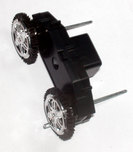
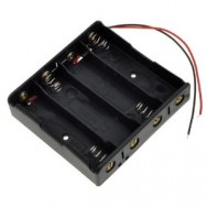
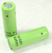
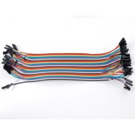
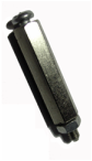
Lihatlah gambar-gambar komponen di bawah ini untuk daftar komponen yang kita butuhkan dalam membuat robot ini. Untuk alat-alatnya seperti obeng dan alat-alat potong standar aja imajinasiin oke..
Lihatlah gambar-gambar komponen di bawah ini untuk daftar komponen yang kita butuhkan dalam membuat robot ini. Untuk alat-alatnya seperti obeng dan alat-alat potong standar aja imajinasiin oke..
|
|
|
|
|
|
|
|

|
|
Blok Diagram
Kita akan lebih banyak membahas lebih banyak membahas lebih lanjut pada bagian-bagian berikutnya. Namun, sebelumnya kita akan melihat dan memahami dulu blok diagram dari Robot Penghindar Halangan ini. Blok diagram akan mempermudah kita dalam memahami bagaimana robot ini bekerja. Komponen yang ada dalam blok diagram di bawah ini yaitu Sensor Ultrasonik, Servo Motor, Motor Driver, Arduino Uno, DC Motor, dan Baterai.
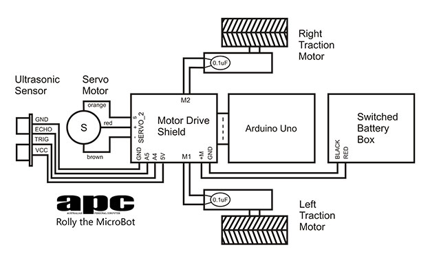
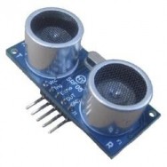
Sensor Ultrasonik memberikan informasi jarak yang akurat sampai ketelitian centimeter. Nah, hasil bacaan sensor ultrasonik inilah yang akan menentukan apakah Robot akan berhenti atau mencari jalan yang lain untuk menghindari halangan yang ada pada jalurnya.
Data dari sensor ultrasonik akan diteruskan ke Arduino Uno kemudian, Arduino akan mengeksekusi program yang telah diupload ke mikrokontrolernya untuk mengendalikan putaran Motor DC. Oke, cukup untuk sedikit tentang teorinya, sekarang kita mulai saja untuk merakitnya..
Data dari sensor ultrasonik akan diteruskan ke Arduino Uno kemudian, Arduino akan mengeksekusi program yang telah diupload ke mikrokontrolernya untuk mengendalikan putaran Motor DC. Oke, cukup untuk sedikit tentang teorinya, sekarang kita mulai saja untuk merakitnya..
Langkah Pertama
Kita menggunakan papan pcb atau plastik sebagai body dari Robot Penghindar Halangan Ini. Rencananya, saya ingin membuat PCB Rangkaian Motor Driver langsung sebagai body dari robot kemudian, tapi karna saya sudah ada Driver Motor DC, kali ini kita gunakan plastik saja sebagai platform dari robot kita ini.
Badan robotnya saya buat dari plastik CD bekas. Kemudian, saya buat polanya sama seperti papan Arduino.
Tips : Ketika mengebor PCB/plastik, atur bor dengan kecepatan rendah terlebih dahulu. Jika sudah ada lubang atau tanda sedikit barulah menggunakan putaran yang lebih kencang. Untuk mata bor gunakan yang 3mm atau 4mm.
Langkah Kedua
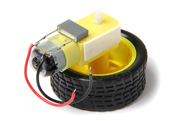
The 0.1uF capacitors have to be soldered across the motor connections and help reduce electrical noise in the circuit, otherwise the Arduino gets a bit cranky. Provided you use ceramic or Mylar capacitors, they have no polarity so just solder one leg to each motor connection tag and do so on both motors. Try to lay the capacitors flat against the yellow gearbox body to keep things neat.
You also need to solder onto the connection tags the wires that go to the Motor Drive Shield. Try attaching them to the capacitor leads if you’re not confident to get everything soldered at the motor connection points. These motors have a D-shaft and wheels that simply press onto the shaft. Use just enough pressure to get the wheel on. After that, cut a small strip of double-sided padded tape, peel back one layer and press it against the motor gearbox, which will mate with the base.
Tip: The motor connection tabs are quite weak, so don’t bend or force them. And take no more than five seconds to solder the capacitors or you might cause the motor connection to break.
Langkah Ketiga
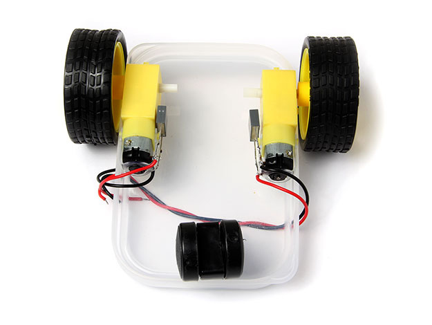
Install the two DC motors to opposite sides of the base using the double-sided tape. Get the motors as close to the edge as possible to allow the wheel free movement
Langkah Keempat
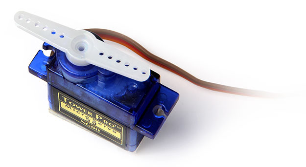
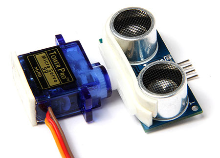
The little SG90 servo motor gives our microbot a neck so it can spin the ultrasonic sensor on its axis. The servo motor itself should come with an accessory pack of attachments called horns. Use the two-sided arm and press it onto the servo motor shaft. You’ll probably need to use a bit of force to get it on the first time, but try not to use too much.
Langkah Kelima
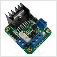
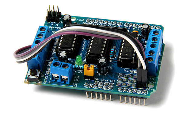
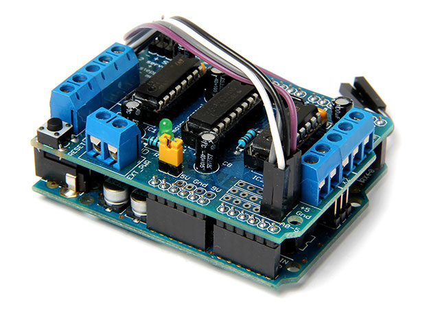
The Motor Drive Shield provides the extra drive power to control the DC motors. It also provides connection for the servo motor and the ultrasonic sensor, for which you’ll need four male-to-female DuPont wires. If you bought a bag of 40 moulded wires, peel four of them off and carefully solder the male ends to the Motor Drive Shield. Solder one wire to the +5V rail, one to the GND pin and one each to analogue pins A4 and A5 down in the bottom right-hand corner. Check the block diagram for pin assignments
Langkah Keenam
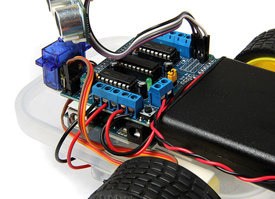
The Motor Drive Shield has a series of pin headers on the bottom of the board — these align with the headers on the top of the Arduino. Align the pins and press the shield onto the Arduino board.
Langkah Ketujuh
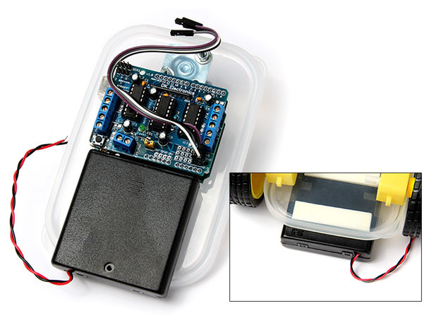
Grab some more double-sided padded tape and add it to the bottom of the Arduino board and the battery box. Note that you want the bottom of the battery box stuck to the base so you can easily remove the top of the box and get at the batteries. Make sure you orient the battery box so the slide switch hangs over the back edge to make it easier to operate. Stick the battery box down first, ensuring the switch overhangs at the back and align the Arduino/shield stack next to it. Depending on the size of the lip of your food container, you may need two layers of padded tape to get the height right.
Langkah Kedelapan
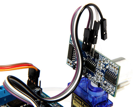
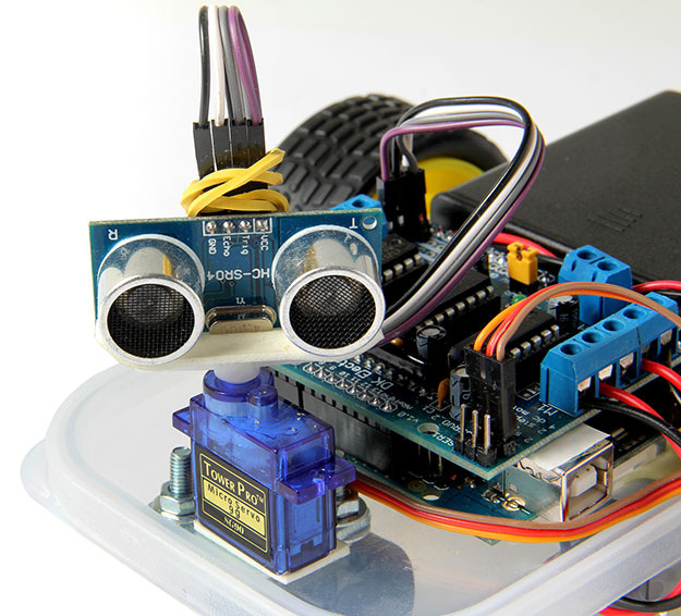
Next, add some double-sided padded tape to the top of the ultrasonic sensor — use enough to wrap around the sides of the sensors for added stick. Make sure the four header pins are pointing up and press the sensor against the servo horn. Add some more tape to the bottom of the servo motor and install it at the front of the base near the caster wheel mounting holes. Connect the servo motor power cable to the ‘SERVO_2’ port at the top-left of the Motor Drive Shield. The orange wire should go to the ‘s’ header pin.
Langkah Kesembilan
Next, connect the female ends of the DuPont wires to the ultrasonic sensor pins. The A5 wire should go to the ‘echo’ pin and A4 to the ‘trigger’ pin. I used a loosely wrapped rubber band to keep the wiring neat and allow enough play to move freely.
Tip: The HC-SR04 ultrasonic sensor is connected to the Arduino’s analogue inputs, although we first program them into digital inputs in our source code.
Tip: The HC-SR04 ultrasonic sensor is connected to the Arduino’s analogue inputs, although we first program them into digital inputs in our source code.
Langkah Kesepuluh
Connect the battery to the EXT_PWR screwblock, but make absolutely sure you get the polarity right or you’ll blow up everything before you start. One of the screw terminals in that block should be labelled +M or +; the other GND. Whichever battery holder you choose, the red wire goes to the +M screw terminal and the black wire to the GND terminal.
The DC motor wires connect to the M1 and M2 screwblocks. The left-side motor wires go to the M1 terminals; the right-side motor goes to the M2 block (you should be able to make this out looking at the silk screening on the top of the Motor Drive Shield.) Don’t worry too much about polarity at this stage — wait until you get to the test run stage and we’ll sort out any polarity issues then.
The DC motor wires connect to the M1 and M2 screwblocks. The left-side motor wires go to the M1 terminals; the right-side motor goes to the M2 block (you should be able to make this out looking at the silk screening on the top of the Motor Drive Shield.) Don’t worry too much about polarity at this stage — wait until you get to the test run stage and we’ll sort out any polarity issues then.
Langkah Kesebelas
Before you install any batteries, check, recheck and triple-check your wiring now. The servo motor header, the ultrasonic sensor and battery box connections must be correct. The DC motor wires are less important.
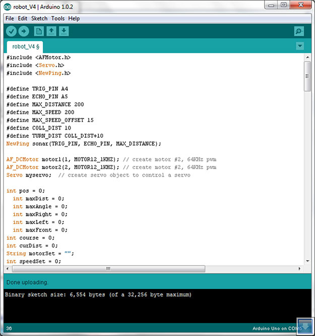
Langkah Keduabelas
Grab the ‘microbot.zip’ source code. Unzip it and copy the contents of the ‘libraries’ folder to the \Arduino-1.0.2\libraries folder on your PC. Copy the microbot folder to your sketchbook folder. Launch the Arduino IDE and you should be able to test-compile the source code. Plug in the USB cable to your Arduino board and in the IDE, go to ’Tools > Serial Port’ and check you’re using the correct COM port. Compile and upload the code to your Arduino board. When it’s completed, you’re done. Not that there’s a problem with the Arduino USB driver on 64-bit Windows 8 systems. We suggest you use a Windows 7 or 32-bit Windows 8 system for now.
Langkah Ketigabelas
When you’re positively sure you have the major wiring correct, install four freshly charged 2,000mAh or better NiMH AA batteries into the battery box (leave the cover off for the time being) and flick the switch, count two seconds and turn it off. The servo motor should move briefly, the LED should light up on the Motor Drive Shield, but the ultrasonic sensor will probably no longer point directly ahead. Don’t worry — this is completely normal. Carefully pull the servo motor horn with the sensor still attached off the servo motor (the padded tape will come with it) and realign the horn so that the ultrasonic sensor is facing directly ahead. When you’re happy with the new alignment, press the servo motor back into position at the front of the microbot base
First Test Run
You’re ready for your first test run. Put the microbot on open ground, flick the switch on the battery box and watch what happens. After a short stutter, the servo motor should swing the ultrasonic sensor in both directions and Rolly should start moving forward. If it’s spinning around on itself, you probably have the DC motor wires incorrectly connected. If it’s turning right, the right-side motor is back to front; if it’s turning left, the left-side motor is wrong.
Once you’ve fixed that, try putting some objects in front of the microbot. If it baulks at them and turns to a different direction, congratulations — it’s working!
What’s next?
If you’re feeling adventurous, try modding the source code. I’ve annotated it all over the place so you should be able to get an understanding of what’s going on, but take your time because there’s a fair bit of code there. We’re actually creating a very crude form of artificial intelligence for our microbot — it’s the code that determines its ‘personality’ or how it responds to its surroundings. Provided you don’t change pin assignments in the source code, try changing other parts of the code to see what happens.
Give it a go!
The best tip I can give is be ready to improvise. As I said right at the start, we’re not building a kit, we’re creating something from scratch, so you may need to adapt the design to fit the parts you have. And that’s perfectly fine because you’re not just learning problem-solving, you’re learning about electronics, microcontrollers and the rest, which will help you with other designs and maybe even spawn a whole new career!
In the 2nd part of this project, we'll look at enhancing Rolly and how to use it to capture mobile video. So watch this space!
Tech corner:
Soldering 101
Our microbot needs a small amount of soldering. If you’re not confident with this, try to find a mate who knows how, or learn. There are plenty of tutorials on the web that will show you how to solder. Just remember, soldering irons get damn hot (over 300°C) so treat them with respect or they’ll bite hard. Jaycar has a beginner’s soldering kit for $25 that would be a great way to start.
Troubleshooting
We’ll look more at troubleshooting in the next article, but here are some brief tips:
Charge the batteries. The Motor Drive Shield needs 4.5V minimum to work and we’re pushing it using just four AA NiMH cells (4.8V), so make sure you freshly charge the batteries to get best results. If the bot seems to continually stutter, you could add a fifth NiMH battery, but we’ve avoided that as five batteries aren’t as convenient to charge as four.
Motor polarity. If the bot seems to go backwards all the time, you may have the motor wires reversed. Just swap them over in the screwblocks.
Look at the code. You’re getting version 4 of my microbot code. Read the comments and learn how it works. You can set the speed and correct for motor speed differences if the bot doesn’t roll in a straight line.
